SCOPE Solution
DUAL COUNTER
SCOPE ACT 5
Prerequisites
Unlocks
sc_a5_03_dual_counter locked
Par power900
Par lines22
Par chips4
Objective
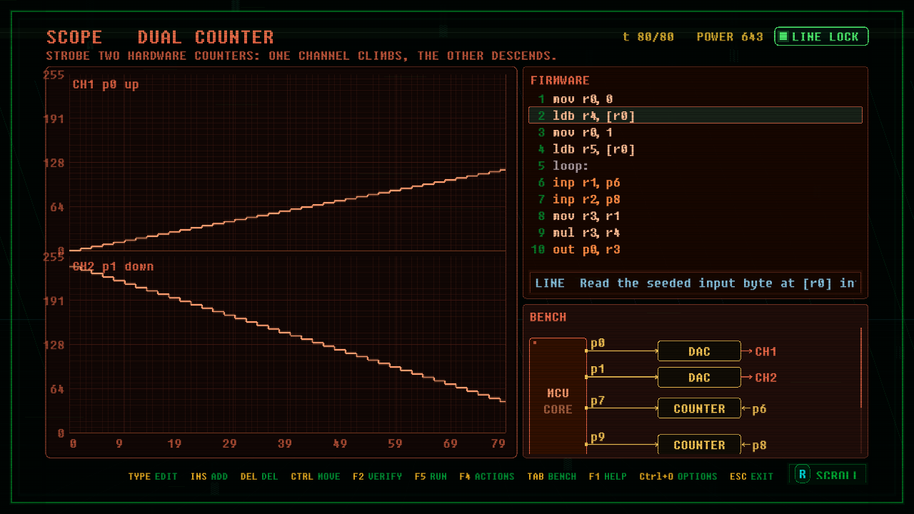
Strobe two hardware counters: one channel climbs, the other descends.
Board Data
- Window: 80
- Pins: p0 OUT, p1 OUT, p7 OUT, p9 OUT, p6 IN, p8 IN
- Channels: p0 ANALOG label=CH1_p0_up, p1 ANALOG label=CH2_p1_down
- Peripherals: DAC data=p0 label=DAC_on_p0, DAC data=p1 label=DAC_on_p1, COUNTER in=p6 strobe=p7 label=COUNTER_A_on_p6, COUNTER in=p8 strobe=p9 label=COUNTER_B_on_p8
Firmware Solution
; DUAL COUNTER reference. Two COUNTER chips tally the strobes on p7 and p9; the
; firmware reads both tallies with inp and shapes them. CH1 (p0) climbs as countA
; times the per-case up step (input[0]); CH2 (p1) descends from a ceiling of 240 by
; countB times the per-case down step (input[1]). The steps are read from the seed,
; never immediates, so the same firmware draws every case in the battery.
        mov  r0, 0
        ldb  r4, [r0]      ; r4 = up step (input[0])
        mov  r0, 1
        ldb  r5, [r0]      ; r5 = down step (input[1])
loop:
        inp  r1, p6        ; counter A tally
        inp  r2, p8        ; counter B tally
        mov  r3, r1
        mul  r3, r4
        out  p0, r3        ; CH1 climbs
        mov  r3, r2
        mul  r3, r5
        mov  r6, 240
        sub  r6, r3
        out  p1, r6        ; CH2 descends from 240
        out  p7, 255       ; strobe counter A up one
        out  p9, 255       ; strobe counter B up one
        slp  1
        out  p7, 0
        out  p9, 0
        slp  1
        jmp  loop
Board Definition
# DUAL COUNTER. ACT 5. SCOPE waveform board.
# TITLE DUAL COUNTER
# OBJECTIVE Strobe two hardware counters: one channel climbs, the other descends.
# Two COUNTER chips tally the strobes the firmware sends; the firmware reads each
# tally back with inp and shapes it: CH1 climbs as countA times the per-case up step,
# CH2 descends from a ceiling by countB times the per-case down step. The battery
# moves both steps (seeded into the input), so a transcript of one pair of ramps
# diverges on the next: only reading the counters and the seeds locks every case.
ID sc_a5_03_dual_counter
WINDOW 80
DIR p0 OUT
DIR p1 OUT
DIR p7 OUT
DIR p9 OUT
DIR p6 IN
DIR p8 IN
PERIPH DAC data=p0 label=DAC_on_p0
PERIPH DAC data=p1 label=DAC_on_p1
PERIPH COUNTER in=p6 strobe=p7 label=COUNTER_A_on_p6
PERIPH COUNTER in=p8 strobe=p9 label=COUNTER_B_on_p8
CHAN p0 ANALOG label=CH1_p0_up
CHAN p1 ANALOG label=CH2_p1_down
CASE phase=3 k=5
INPUT addr=0 label=UP_STEP
INPUT addr=1 label=DOWN_STEP
PAR power=900 lines=22 chips=4